Low Voltage Lighting Wiring In Wall

Four Conductor RGB Power Wire, RGB-4Wire RoHS stands for Restriction of Hazardous Substances. Certain materials used in electronics and electrical products have been deemed hazardous to people and the environment and, therefore, must be limited. For a product to be RoHS compliant, testing must be performed and documented to show limited or no use of cadmium, hexavalent chromium, lead, mercury, polybrominated biphenyls, and polybrominated diphenyl ethers. Download our statement regarding RoHS. 18 AWG Two Conductor Power Wire Five Conductor RGB+W Power Wire, RGBW-5Wire PVC Jacketed 5 Conductor 18 AWG Power Wire PP FRPVC Gray 14 AWG Two Conductor Power Wire Black Jacketed 14 AWG Two Conductor Power Wire White PVC Jacketed UL Type CL2 18 AWG Power Wire PVC Jacketed 4 Conductor 18 AWG Power Wire PP FRPVC Gray 24 AWG Two Conductor Power Wire PVC Jacketed 3 Conductor 18 AWG Power Wire PP FRPVC GrayLow-voltage lighting kits are available at many home centers.

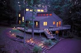
They typically include a variety of lights, 100' of low-voltage cable and a transformer, which converts household current into low-voltage current. Strip the ends of the low-voltage power cable, and connect them to the terminals on the transformer. After you set up the transformer, plan the layout. Depending on the style of the light, you can assemble it and press it into the ground or drive the base into the ground and screw the light onto the base. Some lights have adjustable shades that help you direct the light onto specific areas. Connect the light by clamping the wires to the power cable. Turn on the power to check the electrical connections, and make the final adjustments at night. Although most lights must be assembled, it's easy to put them together. Start by running the wires from the light assembly through the riser base and attach the stake. Insert the light bulb, then attach the lens and cover. Determine how many lights you'll need and where they should be installed.

Then identify the power source, which should be an outdoor GFCI outlet, and determine what other electrical devices are powered by it. Do not overload the circuit. Mount the transformer on the wall near the power source. The transformer should be at least 1' above ground level. If you plan to attach the transformer to a brick wall, drill mounting holes, using a masonry bit, and place plastic or lead anchors in the holes (Image 2). If you can't mount the transformer to the wall, drive a 3' stake into the ground near the outlet. Mount the transformer to the stake at least 1' above ground. Most transformers use timers to turn the lights on and off. Some transformers use photocells to turn them on automatically at night. Once the lights are assembled, and you are satisfied with the placement, dig a shallow trench for the cable (or the cable can be left above ground, if preferred). Run the cable along the trench, and attach the lights to the cable. The lights have clamps with metal teeth that pierce the cable insulation and tap directly into the power line.
Note: Be sure to call your utility company before you dig anywhere on your property. Most companies provide a free service that marks the locations of all underground utilities. Connect the power cable to the transformer, and mount the transformer.
Weight Loss Personal Trainer DallasPlug it in, and set the timer to the "on" position to check the lights.
Dr Branch Weight LossIf all the lights are working, set the timer for the hours you want the lights to turn on and off.
Teak Bedroom Furniture SetsThen go around the lights and bury the cable. Leviton Industrial Wiring Device Selector App The Smart Way to Update your Home State of the Art Security + Protection Leviton Atlas-X1 Connector Overview 30A Stainless Steel Enclosed Safety Disconnect Switch

Evr-Green Electric Car Chargers LevNet RF Wireless Self-Powered Solutions Wall Box (Vizia, Illumatech, Sureslide, etc.) Protect your home and family GFCI's and AFCI's offer different protection. Smart Webinar Series Part XXLeviton's FREE Video Webinar Series Hosted By Industry Experts. Next Webinar: November 17th. Check back soon for registration. Industrial Wiring Device Selector App Find Hospital and Industrial Grade products quickly and easily. Be a part of our industry-leading innovation! You are hereHomeProductsParts and accessories The quality parts used to make our products are available for purchase as single items. Whether you are expanding your system, looking for spare parts, or stocking your maintenance room. Our parts and accessories section showcases those parts we sell individually. If you need something you don’t see please call our sales team or your local representative.One of the best reasons for mounting your new flat panel TV on the wall is the sleek and stylish look that it gives the entire room.

Just look at how it complements our fireplace. What’s not so sleek and stylish, however, are all the cords and cables dangling from below the TV, running across the mantle and down the wall. We’re going to tie into an existing electrical outlet and run new electrical wire and TV cables up through the wall. Once you finish the steps to this video, move on to part two: Adding an Electrical Outlet: TV hook-up. If you’re unsure about working with electricity, you should call a licensed electrician to do the work. But if you’re ready to give it a try, let’s go ahead and get started. Open the breaker box and turn off the electricity to the area you’ll be working in. Use a work light if you need light. Make sure the power is off near the outlet you’ll be working with using a voltage tester. Remove all wall-mounted items from the area that you will be running the wires. Locate the studs and plumbing in the wall using a stud finder. Mark these locations with a pencil.

Measure and draw the lines where you want to cut out the drywall. Then cut through with a drywall saw. Save the cut piece so you can place it back in after the project is complete. Cut a hole through each stud using a right-angle saw and a 1-1/2″ hole saw. This will create a pathway for our plastic conduit tubing. For the electrical cable, we’ll drill a hole 6” above using this 3/4”spade bit. cut a hole for the new electrical box. Also cut a hole near the floor outlet to make the job of pushing the wire through easier. Start pushing the wire through the highest point in the wall and work your way down. Feed the wire and cables through the holes until everything is in place. One of the best reasons for mounting your new flat panel TV on the wall is the sleek and stylish look that it gives the entire room. To hide them, we’re going to run these wires through the wall and up to a point behind the TV where they will be out of sight, hidden from our view.
Today, in this first of a two-part series on wiring a wall-mounted flat panel TV, we’re going to tie into an existing electrical outlet and run new electrical wire and TV cables up through the wall. Then we’ll make a 90-degree turn and route the wiring through several studs before we reach our destination behind the TV. In the next video, we’ll install an electrical box and receptacles and connect the wires and cables. Now before we begin, if you have any hesitation about working with electricity or hooking up electrical components, it’s best to call a licensed electrician to do the work. But if you’re ready to raise your DIY electrical skills a few notches, then let’s get started. The first step when working with electricity is always to turn off the power feeding the circuit you’re working on at the breaker box. You might need to set up a work light plugged into an outlet on a different circuit. Check the outlet with a tester before starting to make sure it’s safe to examine the existing outlet that we’ll tie into.

Lucky for us it’s at the end of a circuit, which will make wiring much easier. This is evident by the single wire cable entering the electrical box. Common types of cable for residential electrical work include 14/2 and 12/2 non-metallic sheathed cable. We’ll use 12/2 because it’s the same gauge as the existing wire supplying the box. The first number represents the gauge of the wire, where the lower the number, the thicker the wire. The second is the number of wires inside the cable. This cable also includes a ground wire. We’ll also take this opportunity to install double-gang boxes at both ends to accommodate both the electrical outlet as well as our TV cable and wiring. But more on that in the next video. After recruiting some help to remove the TV, and taking down anything else in the way, we’ll use this stud finder to locate the wall studs and any other obstacles blocking the path. After investigation, it looks like there are two wall studs we’ll have to drill through en route to our final destination.

We also made sure there weren’t any plumbing or electrical lines in the way. We’ve marked everything with a pencil on the wall so we know exactly where all framing members are located. Now, it’s time to use our drywall saw and cut some strategic holes in our drywall to provide room to drill holes through the wall studs so we can run our wiring and cable. The hole we’ll cut starts directly above the existing outlet and ends near the new outlet that will be placed above our TV bracket. We’ll cut a rectangular strip across the two studs bays and the studs that we’ll be drilling through, making sure to stop the cut at the last stud. This rectangular strip should be about 8”high so we can keep our line and low-voltage wiring at least 6” apart. This will help avoid any possible electromagnetic interference that might occur between the two wires. Using a drywall saw, we’ll punch a starter hole and cut carefully so we can reuse the piece during the drywall repair phase of this project.
Directly over the studs, we’ll use a blade knife. Using our level as a straightedge for our cuts will help. When we removed the drywall, we found that we had two studs side by side, which goes to show that you never really know what you’ll find when you cut away the drywall. In our case it won’t be a problem. Now we’ll use the right-angle drill that we rented from our local independent home improvement retailer and a 1-1/2” hole saw to drill a hole directly through the center of each stud. This will create a pathway for our plastic conduit tubing. For the 12/2 electrical cable, we’ll drill a hole 6” above using this 3/4”spade bit. Be sure to drill these holes as straight and level as possible so the wires or conduit won’t snag as we pull it through. For more on drilling through studs, see our list of frequently asked questions for this video. Now we’ll cut a hole for the new electrical box on the other side of the last stud we drilled through, using the electrical box as a template.

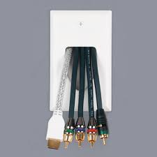
We’ll also cut an access hole to make fishing the wires and cables easier. We’ll premeasure the 12/2 cable so we can see how far we need to feed it down the wall. TV Wall Hook-up (Part 1) At this point we’ll pull the cables through the holes in the drywall we just created. We’ll start at our highest opening on the wall and push the cable down through the stud bay to the hole that will house our new electrical box. We’ll repeat the same process for our plastic conduit, which we’ve pre-loaded with both our HDMI and coaxial cables, taped together at the ends so they won’t slip down into the conduit. If we hit any snags, we’ll use this fish tape to help pull the cable or conduit on through. Now we’ll head across the wall, first with our electrical cable, then with the plastic conduit. There you have it. We’ve got our wiring run and in place. In the next video, we’ll install an electrical box and the needed receptacles to house and connect our electrical wires and TV cables.